Everybody knows that almost everything is possible in narrow gauge and an
increasing numberof self-made "Simplexes", motorized dumper chassis, "Tromobiles"
and other constructions show the crativeness of their authors who, without
exception, follow the same guideline: 't must work!
So, when assembling the boggies for a new passenger coach, the idea of fixing a
motor on one of them came up. A self-propelling coach? Never heard of such a
thing, and after some deliberation I decided that it should be a "genuine"
railcar!
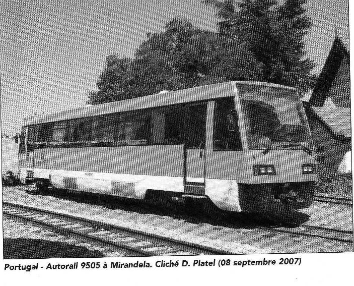
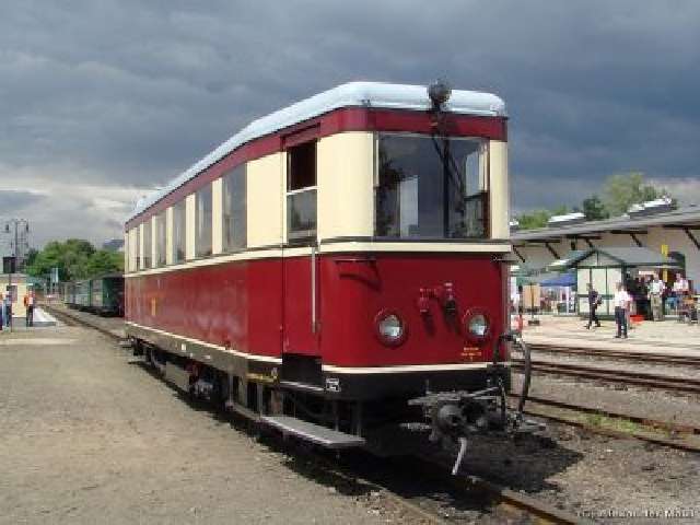
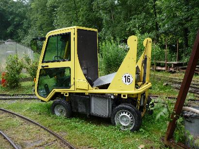
This Portugese metric gauge specimen (left) is what it should be, but I will
certainly have to limit myself to something more simple and more
"vintage" like this 1963 Saxonian VT 137 322 (right) of the 750mm line
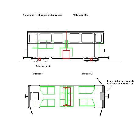
from Zittau to Oybin. The principle, as shown below, is quite clear:
a power unit in the centre of the vehicle and a hydrostatic motor in each boggie,
a command on either end and room for 12 to 14 people.
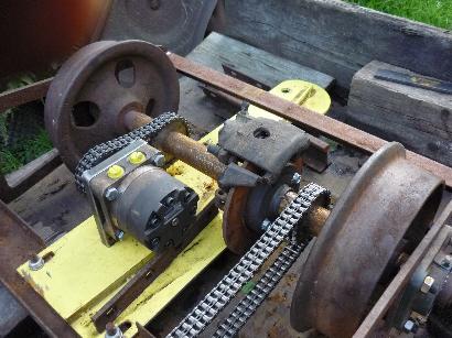
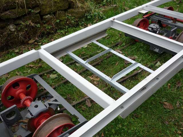
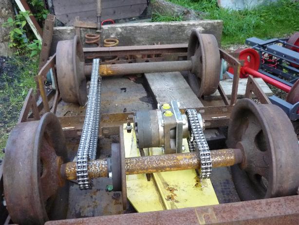 The
hydraulic motor drives the two axles via a Duplex chaindrive. Theoretically, one
driven axle would be sufficient, but seen the conditions on most of the usual
track layouts, a bit more of traktion/braking should be welcome. The disc-brakes
taken from an old Golf II just serve as parking brakes as throtteling the flux
from the pump turns the motors down to a complete stop.
The
hydraulic motor drives the two axles via a Duplex chaindrive. Theoretically, one
driven axle would be sufficient, but seen the conditions on most of the usual
track layouts, a bit more of traktion/braking should be welcome. The disc-brakes
taken from an old Golf II just serve as parking brakes as throtteling the flux
from the pump turns the motors down to a complete stop.
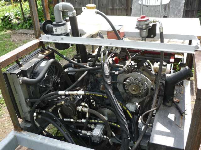
This discarded cleaning machine, once carefully "broken up", provides the
power unit: a 3 cylinder Kubota diesel with a variable hydrostatic pump and two
oil-motors which will get sprocked-wheels instead of the wheel-flanges, even the
instruments, lamps and switches from the dashboard will be reused
First of all, the supports of the dustbinbin are transformed into supports for
the motors.....
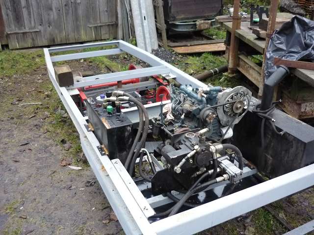
 ...then
the motor/pump unit can be placed on the frame of the rail veghicle, Even the
tanks and the radiator will find their almost original positions. Thus the whole
power unit and its accessoirs can be placed under the central double bench.
...then
the motor/pump unit can be placed on the frame of the rail veghicle, Even the
tanks and the radiator will find their almost original positions. Thus the whole
power unit and its accessoirs can be placed under the central double bench.
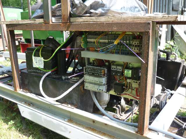
My friend Ludwig Rommel has solved the problem of commanding the vehicle from
the two ends by using a
"Central electric unit" and one single removable control panel.
A specialist of the constructor's advises us in hydraulics and told us how to
neutralize the speed limitation for the "reverse gear". auzuheben
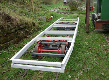
June 2009: Here are the first photos of the frame. In spite of its lenght of 5,00 metres and a width of 1,10 meter the vehicle can take the 7,50 meter radius of the upper curve. The ends of the frame with the future doors are narrowed by 10 cm on both sines (width 90 cm) to come closer to the original aspect of the front.
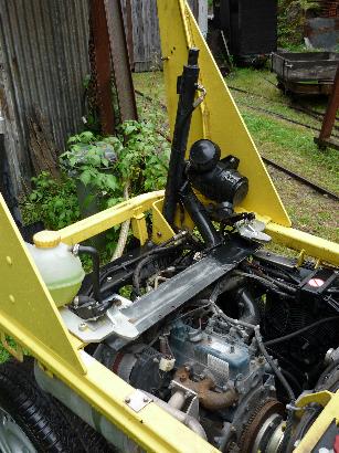
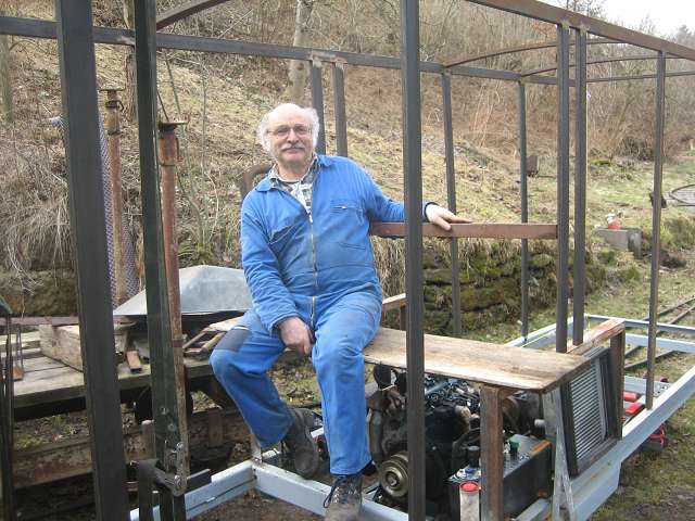
23th November, 2009: The motor is in place and the tanks for the
hydraulic fluid and the diesel fitted to either side of the frame.
The radiator will be added on its support down left. The photo on the right
shows the framework of the central bench with the
air filter, the fluid filter and the expansion ballon for the cooling system
fitted in the future backrests. In the middle, under an orange cover,
the srvo for the pump.
20th March 2010: Because of the extremely long winter I had the
framework for the body made by a (rather expensive) locksmith.
With the help of son Lionel we fitted and welded it home in no time. Special
arrangements will be necessary for the double bench
to allow the air hose and the exhaust pipe to pass from the backrests to the
roof
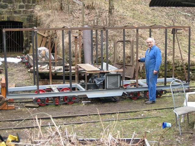
The framework of the body in full length
The central bench is already quite cosy to sit on.....
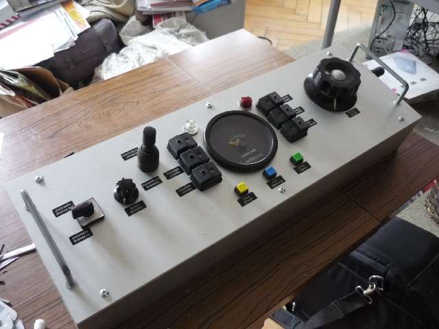
Except for the small button for the engine-speed (left) and the big
The central electric unit contains all the necessary elements for
button for the pump volume (right) all parts of the panel are taken
the engine and the vehicle itself. The control of the engine speed
from the original dashboard of the cleaning engine. The panel
and the output of the pump are done by servo-motors controlled
will be hooked in the corresponding cabin and connected to the
by potentiometers in the panel
central electric unit by a 25-pole-socket and cable.
With all those elements fixed in the central part of the vehicle
and hooks for the control panel added in the cabins on either end, the first
test runs can start
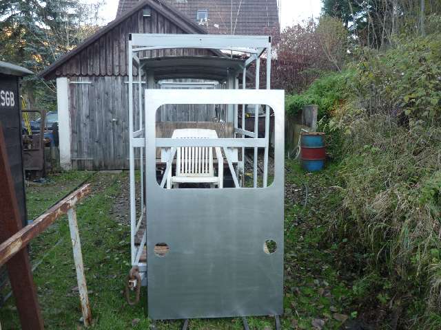
30th october 2010: The two frontpiecs wait for being fixed
(The garden chair is not part of the arrangement!)
According to the progress of the construction you will find more photos and comments here!